Title /
Abstract /
Contents /
Part 1 /
Part 2 /
Part 3 /
Prev./
Next
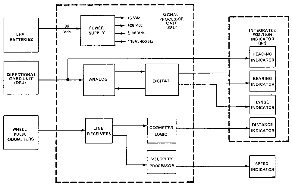
The LRV system accomplished navigation by dead reckoning, with a two-degree-of-freedom directional gyro for a heading reference and wheel pulse odometers for distance information. This information was passed through a Signal Processing Unit (SPU) to yield heading and distance traveled, as well as bearing and range to the initial point of the traverse, near the LM. Figure 17 shows a block diagram of the system components.

Figure 17. Block diagram of LRV navigation system components [from Smith et al., 1973]
To initialize the navigation system before a traverse, the astronauts would park the LRV pointing away from the sun and set the hinged arm of the SSD so that the shadow of the needle fell on the SSD indicator. This reading and the readings of the roll and pitch indicators were relayed by voice to Earth controllers and fed into a computer. Roll and pitch corrections were necessary because of the geometry of the SSD. The computer output the present heading of the LRV, which was relayed by voice back to the astronauts. The astronauts would then manually torque the directional gyro so that this heading was displayed on the IPI compass rose. The internal digital registers of the SPU were then reset to zero by momentarily activating the reset switch. At this time the LRV navigation system was initialized and ready for the next traverse.
The LRV navigation system operated linearly by continuously summing the output of the wheel odometers and resolving this output trigonometrically with the heading angle into north and east increments. In terms of the navigation model, the lunar surface was represented mathematically by a cartesian grid calibrated in kilometers, oriented to lunar North, with the origin at the point at which the astronauts had reset the navigation system.
All four LRV wheels were equipped with rotation sensors with a nine-pulse-per-wheel resolution, each pulse representing a distance traveled of .245 m. As compensation for possible distance measurement errors due to either a dragging or spinning wheel, a circuit in the SPU detected the third fastest wheel and used that information to update the distance traveled.
The Signal Processing Unit consisted of both analog and digital circuitry that navigated according to the following model:
north coordinate = [sum of delta S cos alpha]
east coordinate = [sum of delta S sin alpha]
Wherea (alpha) = heading angle generated by the DGU and analog circuitry in the SPU, and S = .1 km distance pulse generated by the digital circuitry of the SPU. An algorithm called CORDIC (Coordinate Rotation Digital Computer) was used to convert the north and east coordinates into polar coordinates of range and bearing to the point of origin. It is noteworthy that these functions were performed by what amounts to a fairly complicated hybrid analog/digital computer circuit. Such a task could be likely performed today by a very small digital computer, essentially a programmable calculator.
Prev./
Next

