Title /
Abstract /
Contents /
Part 1 /
Part 2 /
Part 3 /
Prev./
Next
External Measurements and Rectification
The navigation system will require additional intermittent references to the external environment besides the continuous measurement of direction and distance; in general this means position fixing and resetting of the azimuth reference gyro.
A position fixing scheme of measuring bearings to landmarks was chosen because the scheme is conceptually simple, and is well adapted to the low-fidelity model. "Landmark navigation", as it is called, requires measurement of azimuth to or of angles between landmarks, therefore an external azimuth measuring system is required. Using measurements of range and azimuth to landmarks is an alternative fixing mode, but ranging equipment is inherently more complex and is not considered here. A scheme using celestial or satellite fixing was not selected because it would be significantly more complex and require the adoption of the high-fidelity navigation model, since celestial and satellite measurements presume the navigator is on the surface of a sphere, not a 2-D plane.
Landmark navigation schemes for lunar surface exploration have been developed and experimented with since the mid-1960's. The specific techniques can be divided into two general categories: fixing using landmarks of known position and fixing using landmarks of unknown position [Hung, 197o].
When landmark positions are known in terms of a given lunar coordinate system (i.e.: lunar latitude and longitude), a fix may be computed in terms of that system. This fixing scenario can be further divided into using azimuth references that are known, as in lunar north; and unknown, such as a reference to an arbitrarily selected point on the horizon. When using a known azimuth reference, a minimum of two sightings to different landmarks is required to resolve a fix. When the azimuth reference is unknown, a minimum of three landmarks is required.
A fix is possible even when the only landmarks available are of unknown lunar coordinates, though all further navigation must be conducted relative to those landmarks and not to a coordinate system. In terms of the navigation model, the environment in this scheme is represented by an unscaled map of the lunar surface, and position is defined by angles to the sighted landmarks. The information yielded is not coordinates, but the direction one must travel in order to get to a previously visited site. This may be useful, for example, in an emergency requiring immediate return to base. To accomplish this method, the navigator must measure azimuths to the unknown landmarks from the present position, and to know what the azimuths to the same landmarks will be when at the intended destination. The process will yield the course to steer to go directly to the intended destination. Once again, when using a known azimuth reference, a minimum of two sightings to different landmarks is required to resolve a fix. When the azimuth reference is unknown, a minimum of three landmarks is required.
A method of reducing errors in landmark fixing is to take more than the minimum required number of observations. The resulting data may be reduced by use of arithmetic mean, least square distance regression, least square solution error regression, or Kalman filtering [Hung, 1970]. Another advantage of multiple measurements is the ability to establish a fix without identifying the landmarks observed. A Kalman filtering program was developed in 1970 which enables a navigator to simply measure bearings to a number of surrounding landmarks and enter those bearings into a computer. The program automatically matches each observation with known landmark coordinates stored in memory. The output is a set of several fix positions which fit the given observations. The navigator then selects which position best matches current location [Lewis, 1971].
Precession of the heading reference gyro will cause loss of fidelity of directional reference. Resetting of the directional gyro must be accomplished by measurement of some external azimuth and by torquing the gyro back to its original orientation. If an accurate current position is known, an azimuth to a known landmark could be calculated and a sighting of that landmark could be used as a reference to reset the gyro. But the relative proximity of any visible landmark to an observer on the Moon could induce unacceptable parallax errors if current position is not known accurately. Measuring the azimuth to a celestial body such as the Sun or Earth provides a viable alternative, and can be accomplished with azimuth measuring equipment and a computer program to calculate the current azimuth of the Sun or Earth.
It should be pointed out that azimuth measurement must take into account the observer's local vertical. Measuring azimuths to distant objects from a tilted surface will induce error in the azimuth measurements. The Apollo Lunar Rover was equipped with pitch and roll sensors to compensate for this fact when setting the directional gyro [Smith, 1973]. The azimuth measuring equipment must therefore have a vertical sensing capability to compensate for the vehicle's current attitude while fixing.
Typical System operation
After power is applied, the system must be provided with initial position and current heading. In the Apollo LRV, initialization consisted of setting the initial heading using an azimuth reference to the Sun, and the initial coordinates were set to (0,0) [Smith et al., 1973]. All navigation information generated by the system was in relation to these initial coordinates. However, the LRV was limited to simple out-and-back missions with no enroute fixing capability. For greater mission flexibility, the system should be able to accept lunar latitude and longitude for initialization and for landmarks used in fixing. Since the low-fidelity model is of an unscaled coordinate system, the system must translate lunar coordinates into model coordinates.
The directional gyro must be initialized as well, and this would be accomplished by calculating the current azimuth of a celestial body (most likely the Sun or Earth), sighting of the body, and applying corrections for local vertical. The gyro would then be torqued to the vehicle's current heading based on the measured azimuth.
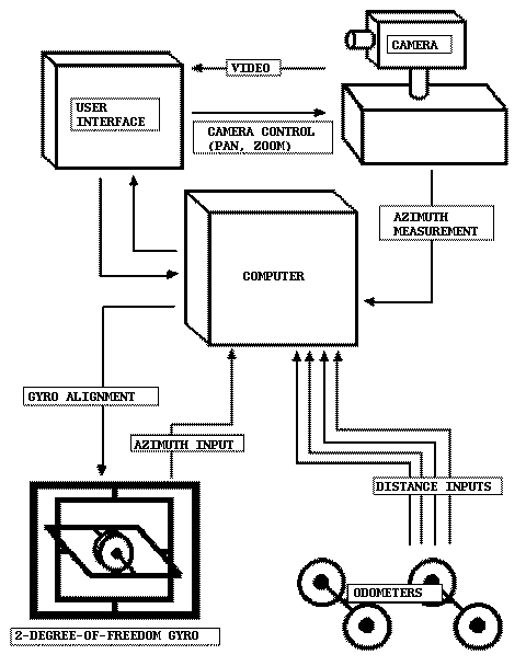
Enroute, the system will perform automatic dead reckoning. Over time, position error will accumulate and the gyro compass will precess. Part of this error will be due to equipment inaccuracies, wheel slippage, etc. Another part will be due to the low-fidelity model itself: As the vehicle moves farther from the initialization point, the position on the 2-D model will less and less accurately reflect the vehicle's true position on the lunar sphere. When the sum of these errors have reached unacceptable levels, the vehicle must halt to take landmark fixes to update position, and celestial azimuth sightings to update the directional gyro. Figure 7 is a schematic of the system.
Advantages and Disadvantages
The primary attribute of this system is that it is relatively simple. Appropriate components could make this a very lightweight, low power, reliable navigation device useful mostly for local area navigation. Its basic components; odometers, a celestial azimuth sensor, and a computer; are already in existence, so development would only require adapting existing technology to the mission at hand. But it is by no means an optimum design. The main disadvantage being that it would lose fidelity fairly rapidly on long distance excursions unless frequent fixes were calculated.
The advantage of an odometer system is that it is very simple, cheap, and reliable. On the other hand, any system which uses wheels rolling on the surface to measure distance will incur several errors. One error is wheel slippage, a result of imperfect traction between the wheel and the surface. If the wheel used for measurement is a drive wheel (a wheel to which a motor is applying torque), slippage may cause more rotations to be counted than is representative of the actual distance traveled. If the measured wheel is a non-drive wheel, slippage may cause fewer rotations to be counted than is representative of the distance traveled.
Another potential error occurs when the vehicle is turning: a wheel on the outside of the turn will measure a greater distance than one that is on the inside of the turn. Theoretically, if the turn is sharp enough, the inside wheel could cease rolling altogether, or even roll backwards [Hung, 1970].
Possible Improvements
To help counter these errors, we could take measurements from more than one wheel, or we may employ an odometer wheel independent of the main wheels of the vehicle, as was done in the Lunokhod vehicle [Wilson, 1987]. Whatever method is used will require careful consideration. For example, simply averaging the odometer readings from several wheels would not work if one wheel happened to be jammed or dragging. The Lunar Rover avoided this possibility by accepting only odometer inputs from the third fastest wheel[Smith et al., 1973].
Another error results from applying measurements of travel over the three-dimensional lunar surface to a two-dimensional model. This error works on a continuum of scales. On the largest scale is the fact that the curvature if the Moon itself induces mapping errors in a two-dimensional model. This is the classic problem faced by cartographers in projecting a spherical surface onto a two-dimensional map. On a smaller scale, the lunar surface deviates from ideal flatness due to elevation changes. Consider a straight-line journey across hilly terrain. On a flat, two-dimensional surface, this trip might be one hundred miles long. When measured by odometer, however, the distance may be 105 miles, due to the extra distance traveled in vertical displacement. The vehicle would roll farther than the actual horizontal distance traveled. On yet a smaller scale, the myriad bumps and granulations of the lunar surface would also add error to the measured distance.
Spherical mapping error may be compensated for mathematically, based on the type of projection used. But the best option would be to resort to the high-fidelity navigation model, which would, for all practical purposes, eliminate spherical mapping error. Mountainous terrain could be compensated by applying elevation data to the model and applying the distance measured by odometer to these corrected charts.
Smaller scale surface roughness can be compensated for mathematically by considering roughness in terms of cycles per meter. From this perspective, surface roughness can be defined as a continuous spectrum of frequencies and analyzed statistically. The resulting "spectral density function" can then be applied to odometer measurements. This was incorporated into the design of the Apollo Lunar Roving Vehicle [Hou, 1971].
Prev./
Next