Title /
Abstract /
Contents /
Part 1 /
Part 2 /
Part 3 /
Prev./
Next
HIGH-FIDELITY DEAD RECKONING SCHEMES
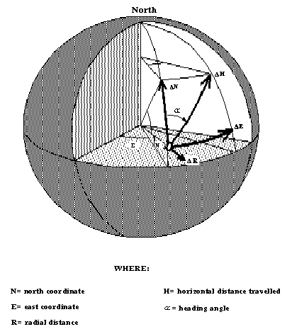
As indicated in Figure 8, the high-fidelity navigation model attempts to reproduce the actual lunar sphere with a 3-dimensional coordinate system of latitude, longitude, and radial distance from the center of the sphere. Likewise, the movement of the lunar vehicle is represented in three dimensions as well, and these movements must be modeled in a three-dimensional dead reckoning scheme.

Figure 8: High fidelity navigation model
Mathematically, dead reckoning is the technique of integrating a vehicle's velocity vector with respect to time in order to maintain a continuous measure of vehicle position [Hung, 1970]. Unfortunately, establishing the vehicle's velocity vector is significantly more difficult than measuring heading, as in the previous system. Slipping and skidding have already been mentioned as sources of error in measuring a displacement vector based solely on heading. Another source of error that is inherent in the previous system is that there is no measurement of the vertical component of velocity, only the horizontal X and Y components. Considering these factors, a system capable of determining the vehicle's velocity vector must be able to sense the vehicle's displacement in 3-dimensions. The previous system is not capable of such measurement, even with the addition of a vertical sensor, since the overall system does not sense any slipping or skidding. A system that is capable of such measurement is the Inertial Navigation System, or INS.
A complete discussion of inertial navigation theory is beyond the scope of this project, but the fundamental concept behind inertial navigation is still essentially dead reckoning, but of a higher order.
In the dead reckoning system described previously, horizontal displacement was measured directly through the use of odometers. Alternatively, the odometers could be used to measure velocity, and this converted to horizontal displacement (H) by integration with respect to time:

Likewise, one can measure acceleration, and using this information determine displacement:

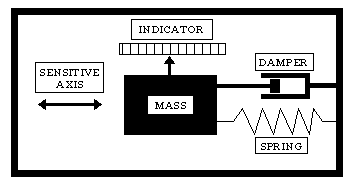
Acceleration is measured with an accelerometer, a device that measures the linear displacement of a spring-loaded mass. The specific arrangement of an accelerometer may vary, but a generic representation is given in Figure 9.

Figure 9: Schematic of an accelerometer.
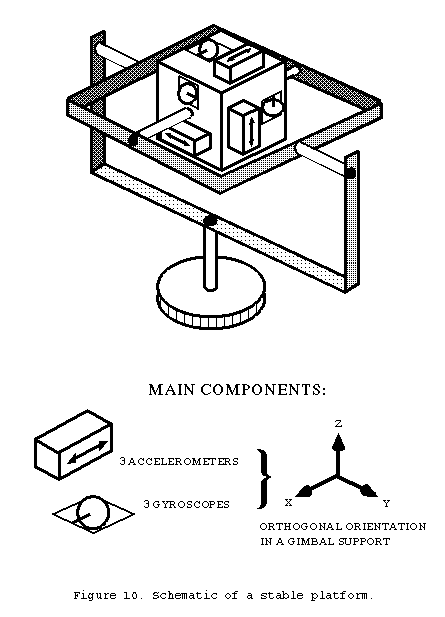
Three accelerometers mounted orthogonal to each other are required to sense acceleration in three-dimensional space. Gyroscopes are required to maintain these accelerometers in an stable orientation, so that each accelerometer consistently measures acceleration on the same inertial axis. Unlike the previous system, gyroscopes in an INS are of the single-degree-of-freedom type. The primary characteristic of the single-degree-of-freedom gyroscope is that its sensitivity to rotation is confined to only one axis. Three single-degree-of-freedom gyroscopes mounted with their sensitive axes orthogonal to each other are required to sense rotation about the vehicle's three axes of rotation. In an INS, such a configuration is combined with the three orthogonal accelerometers and the whole assembly is itself is mounted in a gimbaled frame. Signals from the gyroscopes drive torquing motors in the gimbaled frame and thereby maintain the unit, along with the accelerometers, in a fixed inertial orientation. The assembly of accelerometers, gyroscopes, and gimbaled frame is known as a stable platform, and is depicted in figure 10. Accelerometer outputs are double integrated to yield displacement along three axes, and the three outputs are continuously summed by a computer, producing coordinates in three dimensional space.

Obviously, an INS is mechanically very complex, hence prone to breakdown and expensive to manufacture. Some of this complexity can be reduced by the use of a strap-down INS. Such a system eliminates the stable platform, but retains the gyroscopes and accelerometers. The gyroscope signals are used as a source of attitude information, which a computer uses to calculate the x, y, and z components of acceleration from each accelerometer. The price of this lack of complexity is that the strap-down system, as its name suggests, is directly attached to the vehicle frame, and thus exposed to greater mechanical shock than a system isolated in a stable platform. This is a significant factor affecting the construction and maintenance of mechanical inertial systems; but recent technological advances may dramatically reduce or even eliminate this problem with the advent of solid-state inertial systems, which will be discussed in the third section. But considering the INS as a mechanical stable platform will suffice for conceptual purposes.
Prev./
Next